The Expanded Railroad Glossary Part 5 in Tales of the Jointed Track
- Sept. 16, 2014, 10:49 a.m.
- |
- Public
EMD air box :
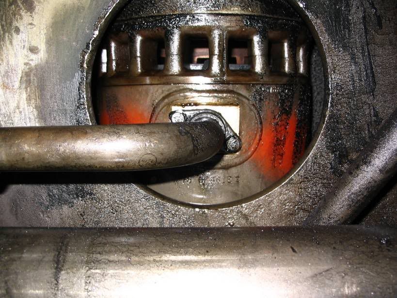
looking inside the air box of an EMD 567 or 645 cu in diesel engine. The cylinder liner is in view..the ported area ( looks like little windows ) is where the combustion air comes into the cylinder. You can see the piston top. The odd pipe is the “jumper line” The pipe below is the main water line. The jumper sends water into the water jacket surrounding the cylinders. You get one jumper per cylinder. When I talk about a jumper line leak, it happens here. The gasket behind the flange can leak, or the flange welds can break. We’re talking extreme heat in this area.
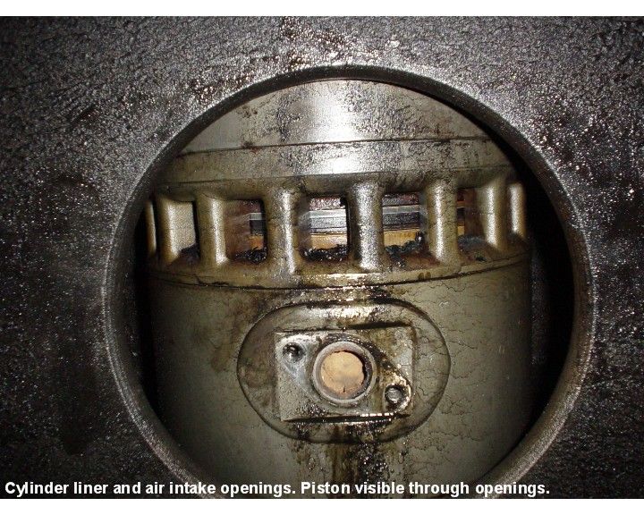
This is a ported cylinder with the water jumper removed. you can see the piston rings in the ports. The grime is combustion grime, lube oil etc. The air box has small drains, and the main air box drain removes this accumulation, without severely depressurizing the air box. The entry with train 152 in cold below zero weather address this.
Ported Cylinders:
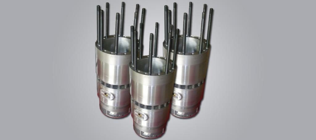
These are new or reconditioned EMD ported cylinders. You can see the studs where the cylinder head will attach at the top. The ports for combustion, and the access for the water jumper line.
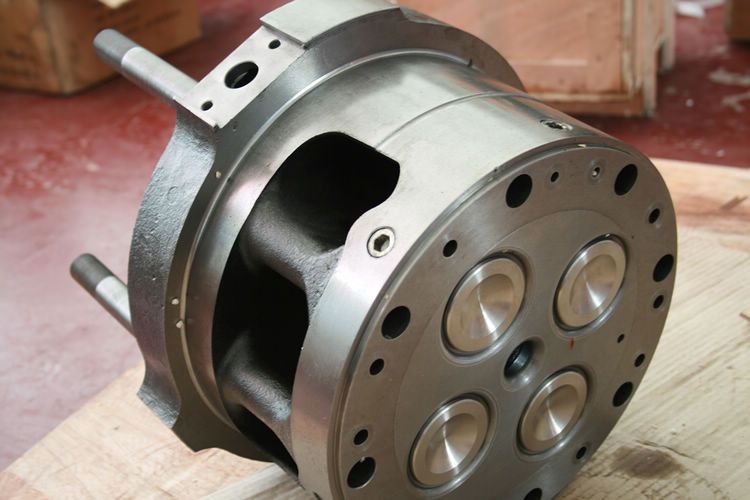
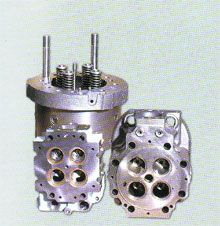
* You can see a new EMD Cylinder head. The large ports to the top left, are the exhaust ports to the exhaust header. The four silver looking valves, are that exhaust valves. The small center hole is where the injector is located. The holes in the outer circle are the water inlets, via the jumper line that is attached to the cylinder liner. Gaskets and rubber grommets seal the head to the liner. *
Fork Rods and Blade Rods:
These are what attach the piston assembly to the crankshaft. There is a blade rod that “floats” on the crankshaft. The Fork Rod encapsulates the Blade Rod and both then are fastened at the bottom, with what is called a basket. The bearings are in between the fork and blade rods and the basket. These are torqued in to tolerance. The engine will be “barred” over to ensure that there is no binding or fouling.
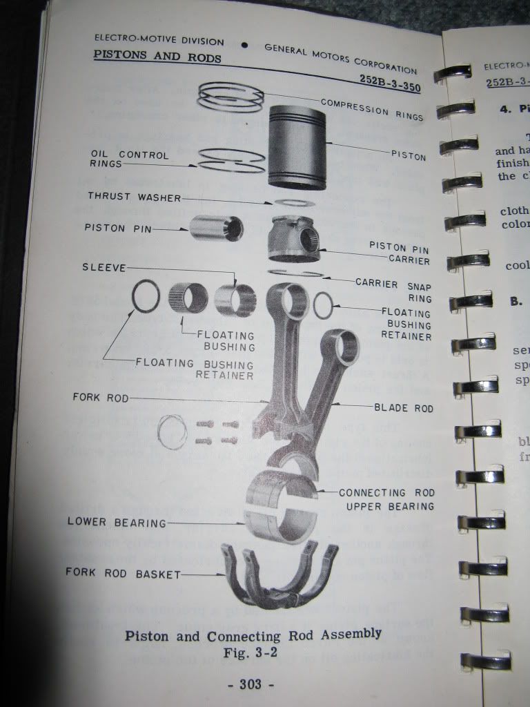
A schematic of how these all fit together
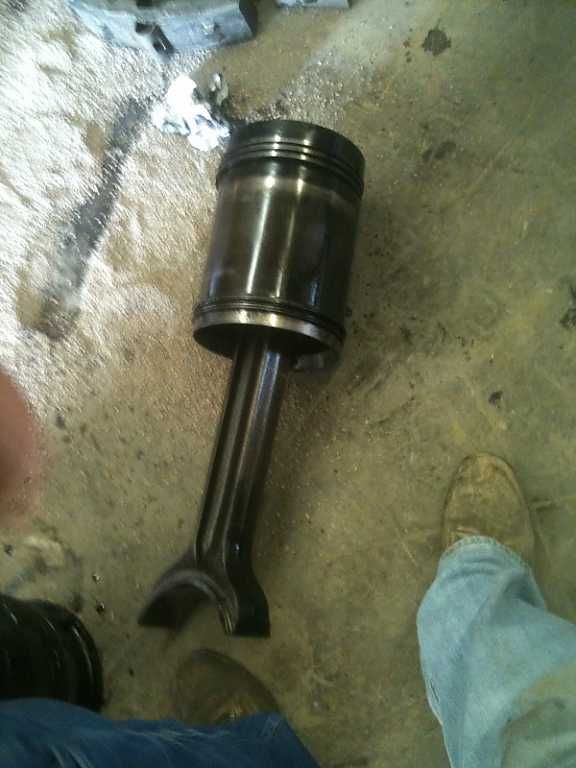
Piston attached to the blade rod. Looks like have just removed it from the cylinder and engine bank.
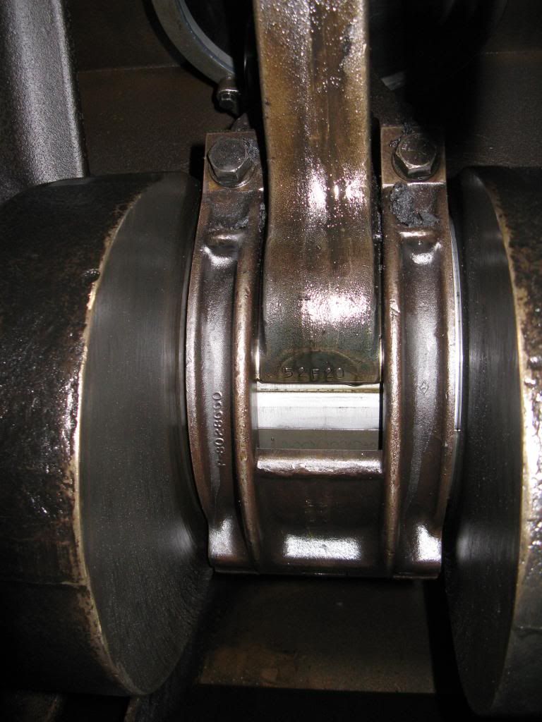
A view of the Fork and Blade Rods assembled with the basket to the crankshaft.
Pee pipe:
This is an instrumental part that aids and induces lubrication to the Carrier bearing, and cools the piston crown.
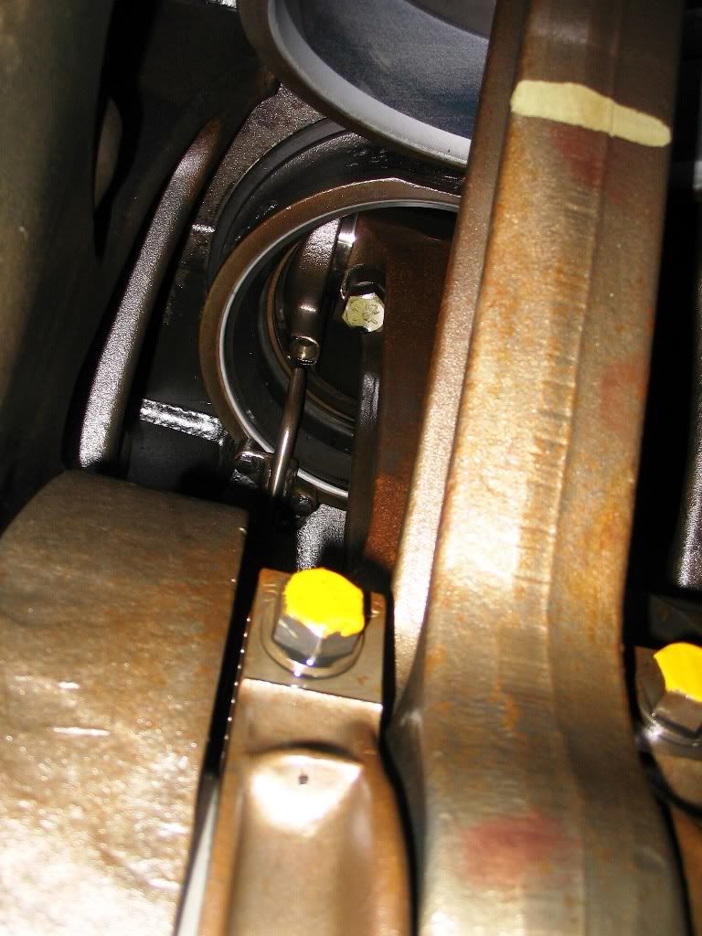
If you look just above the yellow cap screw bolt slightly to the left you’ll’ see the Pee pipe. The hole just above, is where the piston assembly comes over this on the down stroke.. This is like a continually running oil fountain, while the engine is running. This forces and injects oil into the piston from the bottom, cooling the top or piston crown. It also lubricates the carrier bearing and associated rod bearings too.
Carrier Bearing:
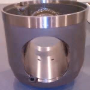
This is what it looks like. The connecting rod ( fork or blade ) are attaced by a wrist pin placed in the large hole in the side. If you look top left slightly offset, you’ll see the hole for the pee-piping access. This carrier is attached to the piston via a large snap ring.
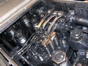
This what it all looks like on the inside of the top deck. You can see the rocker assemblies, the two outside ones operate the exhaust valves. The center operates the fuel injector. The piping is the fuel intake and return lines. This does two things admits fuel into the injector and also lubricates the internal parts of the injector. The remaining unused fuel is returned to the fuel tank to be used again. The Large bolts and studs you observe are the Crabs and the Crab Studs. These hold the Cylinder liner and head into the engine bank. These are torques in at the final tightening at roughly 1100 ft pounds with a multiplier torque wrench



MageB ⋅ September 20, 2014
WOW....thanks too for putting the assembly in size scale next to your foot.