The Expanded Railroad Glossary Part 2 in Tales of the Jointed Track in Tales of the Jointed Track
- Sept. 1, 2014, 10:50 a.m.
- |
- Public
-
ABS Automatic Block System:
A series of consecutive blocks governed by block signals, cab signals, or both, actuated by train or by certain conditions, affecting the use of that block. -
Railroad Company Abbreviations:
ATSF - ATCHISON TOPEKA & SANTA FE ALSO KNOWN AS THE SANTA FE NOW
BNSF- BURLINGTON NORTHERN SANTA FE RAILWAY
D&RGW -DENVER AND RIO GRANDE WESTERN ALSO KNOWN AS THE RIO
GRANDE OR THE GRANDE
C&S - COLORADO AND SOUTHERN NOW PART OF BNSF
UP - UNION PACIFIC RAILROAD
KCS - KANSAS CITY SOUTHERN
BN - BURLINGTON NORTHERN A MERGER BETWEEN THE GREAT NORTHERN,
NORTHERN PACIFIC, CHICAGO BURLINGTON & QUINCY, AND SPOKANE
PORTLAND AND SEATTLE
GN - GREAT NORTHERN
NP - NORTHERN PACIFIC
CB&Q - CHICAGO BURLINGTON & QUINCY
SP&S - SPOKANE PORTLAND AND SEATTLE
SP - SOUTHERN PACIFIC -
Control Stand: The operations part of the cab, that the engineer can control the locomotives with throttle and dynamic braking, and the air braking as well.

EMD SD-40-2 control stand BN 7908 I probably ran this in my career.
left to right Top left AAR multi channel radio Automatic brake valve ( shows cut in and a full service application) Independent brake valve ( fully applied). Whistle or Horn button Yellow button alertor reset/ acknowledge Small toggle lead truck sand Consist sand just below ( some one unscrewed the bail lever,,I hated that !!) Gauges left to right Brake pipe white needle and Main Reservoir red needle BP is at 70 lbs or a 20 pound set Main Res is around 130 lbs. Second to the left Equalizing reservoir white needle (Equalizing reservoir is at 70. This is where you set the amount of air you want on the train. The brake pipe will follow at a service rate. Independent brake pressure red needle (locomotive brake(s) only) Shows at 72 lbs a full set. Second to the right the Flow Meter. This tells you the rate of charging to the Auto brake valve in CFM ( cubic feet per minute ) this is the draw of the main reservior Far right is the AMP Gauge It is showing zero due to no throttle or dynamic braking being used. To the right of zero is power amperage. to the left is dynamic brake amperage The top lever is the Dynamic brake the middle is the throttle The reverser is below and in the neutral position. Forward is to the right. reverse is to the left. The two switches either side of the reverser are the rear and forward headlight control Off-Dim-Med-Bright.
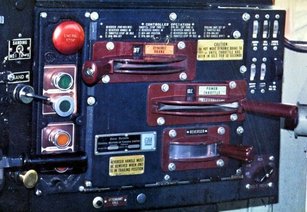
This is the same as the above explanation, except for the air brake push buttons for the old RCE control. RCE was the predecessor of the Distributive Power (DP) used today The BIG RED Button was the emergency brake. The green push button was to set the automatic brake valve. Push one then an initial or minimum reduction was made. The you pressed off an increased application as needed. The button below, was a pull only, that released your set. The top orange button was the independent brake set. the bottom was the release and the “Bail Off” function for the independent.
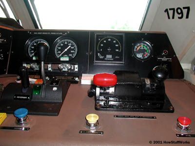
The “Desk Top” control stand that became standard after 1990. They were never my favorites. The gauges are the same. You can see the throttle and reverser. Throttle is pulled toward you positions 1 thru 8. Dynamic Braking push forward to set up the positions 1 thru 8. The Red Handle is the Automatic brake valve. the rounded black handle is the independent brake valve.
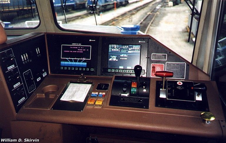
This is a desk top SD-70 MAC control stand with the dual screen. The left screen is a dual purpose screen. It can show diagnostics or if equipped be a Distributive Power screen. The Right screen is the main power screen and air brake control set up. The soft key buttons access different parts of the screens as needed. The big Black Square above the yellow blue and white push buttons is the pacesetter mode for loading coal, or to dial in a certain slow speed operation..
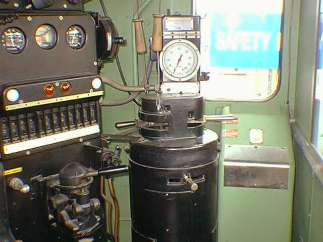
Although no longer used this is an old style control stand used on the old GP-7 and 9’s , SD-7- and 9’s s, and the F-3 . 7 and 9’s What ever exists today is at an operating railroad museum.
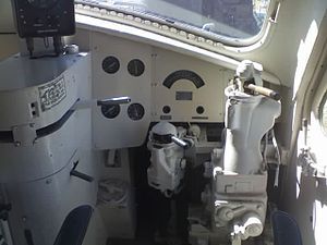
This is a control stand of the E-6,7,8 and 9 locomotives used for passenger service
The throttle is the long lever at top the reverser is at the bottom. The “Square” left of the throttle quadrant, just to the left of that is another lever not shown. That is the transition lever and also allows the locomotive to be placed into dynamic braking. The four round gauges are the standard air gauges and steam boiler pressure for the Vapor Clarkson steam generators or heat and air conditioning of the coaches. The rainbow arced gauge is the amp gauge. The tall valve is the automatic brake valve. the little rounded top valve is the independent brake valve.


MageB ⋅ September 07, 2014
This is a most amazing effort on your part. Thank you....I actually understand all this tho I will have to read several times to remember it. The different desktops and controls will take more effort of memory on my part. Thanks.